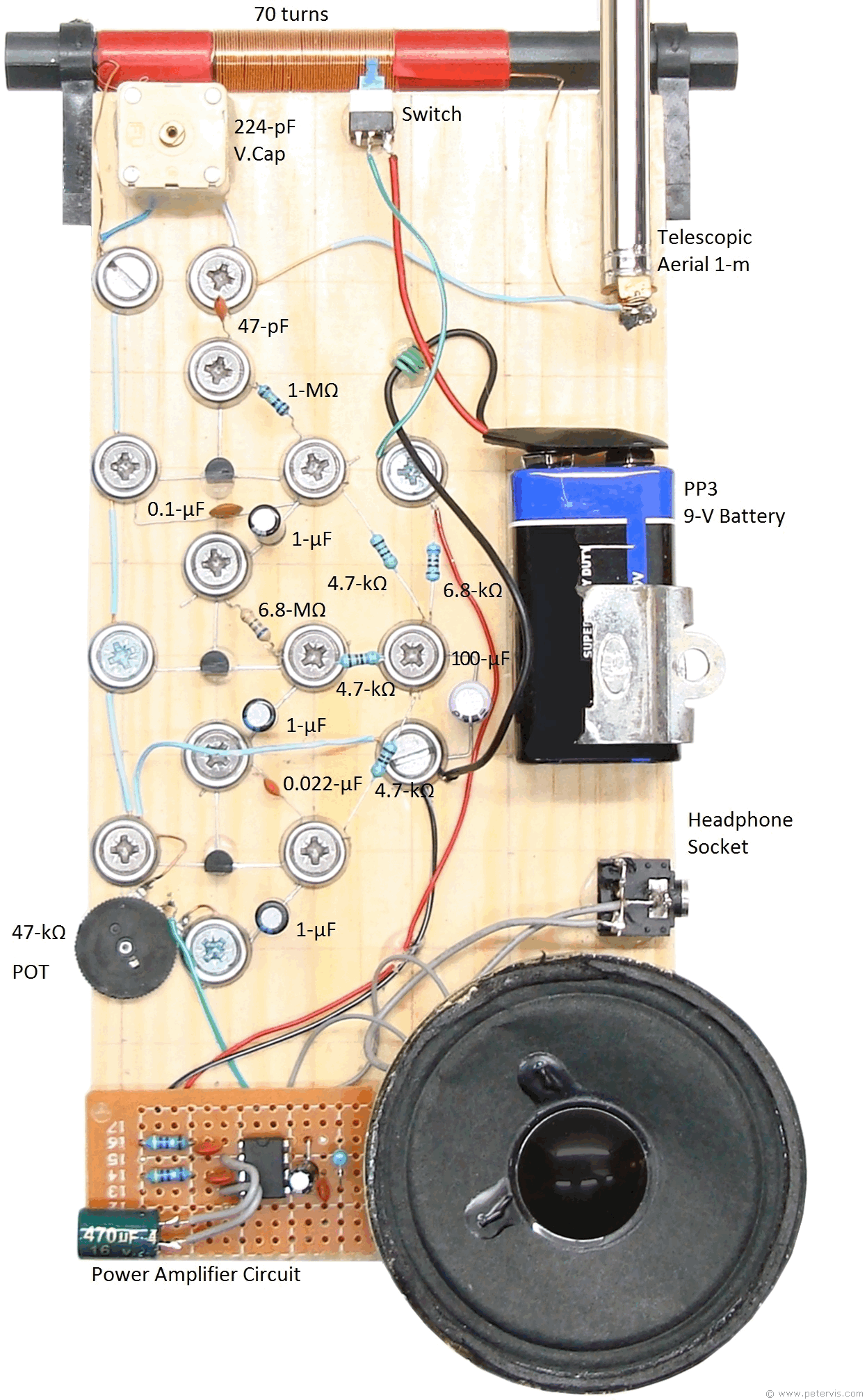

The greater the Q, the more selective the circuit becomes. The ratio of this dynamic impedance to any loss resistance present is called Q. If they are in parallel (as in our circuit), the combined impedance is very high, and if they are in series, resonance also occurs but the combined impedance is very low. When the reactance (AC resistance) of capacitor C2 is the same as the reactance of the coil L1, resonance occurs at the frequency f=1/2π√(LC).įor example, with L1 equal to 300 uH and C2 equal to 100 pF:į = 1/2π√((0.0003 H)*(0.000000000001 F)) = 919kHz. What’s truly amazing here is that this circuit will work without any batteries and provide hours of AM listening fun. Use magnet wire to wind the coil if possible.įor this radio work well, you will need a good earth connection and at least 20m of wire as high as possible outdoors as an antenna. The tap is at about 5 to 10 turns to be coupled to the antenna. L1 is a coil wound on a ferrite rod with about 50 to 60 turns.

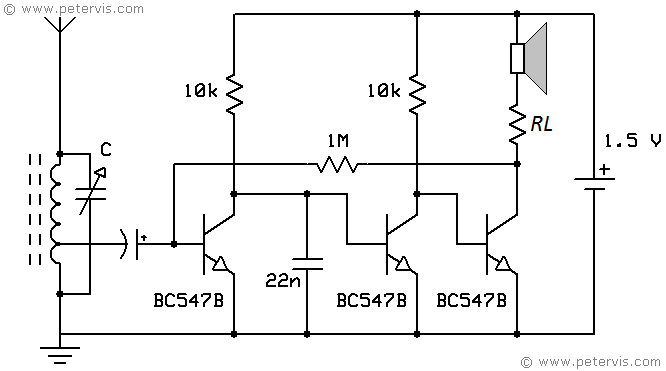
The LS is a high-impedance piezoelectric headphone like the vintage 2000Ω “crystal earpiece”.Ĭapacitor C2 is a variable capacitor of about 300pF to 500pF. But any diode will work, only with less volume. The diode is ideally a germanium diode, like the OA81, as it has a lower forward volt drop. Building this is an excellent start in understanding how AM radios work: Shown below is a simple (and magical if you have ever built one) crystal radio circuit. AM is also used on all aircraft radios from 108 to 136MHz. This means that the transmitter radio (or carrier) signal is modulated with the music or speech content in a manner that the amplitude of the carrier is varied in relation to the incoming speech or music. Radio stations in the medium wave and short wave bands transmit their signals using Amplitude Modulation (AM). AM receivers are also simple and easy to build. But they are still popular as they have more channel space than FM stations and offer longer range coverage, especially at night via the ionosphere. Medium wave and short wave were the main broadcast radio bands until the advent of FM. On the other hand, short wave extends beyond that and up to about 30MHz. This eliminates the need of an external switch to be associated with the circuit, making the unit very compact.Medium wave is a band of radio frequencies extending from 530kHz to 1700kHz. When connected, the received signals can be distinctly heard over the headphones with this little “audio marvel”Plugging in the headphone initiates the circuit and the circuit starts operating with its functions and the switches OFF itself when the headphone is removed from the circuit. Headphone Becomes the Load and the SwitchĪ 64 Ohm headphone becomes the collector load of the transistor, where the demodulated and amplified signal is applied. The coupling capacitor at the base of the transistor makes sure only the radio information passes to the transistor while the DC component from the supply is appropriately blocked. The concentrated but very low in power signal from the above LC tuned stage is fed to the base of the transistor which as performs the function of a demodulator as well as a amplifier stage. The coil is tuned using a GANG condenser or a variable capacitor which is connected in parallel to the antenna coil.The coil and the GANG together form a resonant tank circuit, which lock on to the received or the resonant frequency at a particular setting. The figure below shows how the single transistor radio can be made, we can clearly see that it just involves a single transistor as the main active component.A regular type of MW antenna coil has been used for collecting or sensing the MW receptions. However simplicity will always involve some drawbacks also, here the present design will be capable of receiving only strong stations and also selectivity might not be very pleasing, typically if there are a couple of strong stations mingling around the band. The circuit of a single transistor radio shown here though looks pretty ordinary, yet incorporates all the above stages and becomes just suitable for receiving the nearby radio stations.

What are the fundamental criteria associated with radio reception? An antenna stage, a band selector stage, a demodulator stage and a receiving element.When all of these come together radio reception becomes as simple as a piece of cake.


 0 kommentar(er)
